A two-channel 120Wchannel Class D reference design fits on a 15 x 3125 PCB requires no heat sink and locates all components for the Class D switching stage on the boards top surface. G D S f0 Class B Class C 65-6dB 8 dB 78 PA.
Fundamentals Of Class D Amplifiers Maxim Integrated
48 EER Envelope Elimination and Restoration.
. A Class D amplifiers high efficiency makes it ideal for portable and compact high-power applications. As mentioned previously efficiency is proportional to power level and low power levels generally mean lower efficiency. 1 day agoAudio AMP Class D - PWM Output to RC Filter.
RF Power Amplifier Design Markus Mayer Holger Arthaber. 2 Contents Chapter 1. 1 Feb 2006 pp.
RF output high efficiency power amplifier digital signal processor local oscillator supply voltage amplifier I Q I Q di gi ta l b a s e band i npu t. Ad Discover MERUS our top performance audio amplifier solution. Class D Amplifier Design Basics II 02192009 Rev 10.
For example a Class-B or -C power stage operating at 65 collector or drain efficiency losses 35 of input power. RF Power Amplifiers are used in a wide variety of applications including Wireless. 40 48.
Typically Class-E amplifiers 1-6 can operate with power losses smaller by a factor of about 23 as compared with conventional Class-B or -C amplifiers using the same transistor at the same frequency and output power. The Class D amplifier depicted in Fig. - Selection from RF and Microwave Transmitter Design Book.
Bootstrap High Side Power Supply High-side ON Low-side ON After the high-side MOSFET ON state I. A 300 W 1356 MHz Class-D circuit is designed in the traditional manner to illustrate the magnitude of the different types of loss. A drain efficiency of 80.
New 100 Watt 3 dB 50 ohm Hybrid Attenuator up to 2 GHz. The losses analyzed are the switching conduction and gate drive losses. Up to 5 cash back 11 High-Efficiency Power Amplifiers High efficiency of the power amplifier can be obtained by using Class D Class F or Class E operation modes and their subclasses depending on the.
Download Free Advanced Design Techniques For Rf Power Amplifiers ameamericansamoagov. Many modern Class D amplifiers however utilize advanced modulation techniques that. In order to further improve the efficiency this design optimizes the MOS full bridge circuit of the post power output making the efficiency of the power amplifier reach 918 which is much higher than the traditional class D audio power amplifier.
In class-G operation the TDA7901 buck controller automatically optimizes the voltage supplied to the. When considering the power. Technologicaly Advanced High Power Solid State RF Microwave Amplifiers 18 GHz and below.
No one class of Buy 180W HF linear high-frequency radio frequency power amplifier amateur radio station parts online at an affordable price. Low-power operation requires more care in the design of Class D amplifiers. The Sinclair X-20 in 1966 produced 20 watts but suffered from.
Infineon - Connecting the real and the digital world. A circuit using the ZVS equations developed in this. In class E amplifiers the key ele-ments are the transistor which is modeled as a switch and a shunt capacitor.
Class F and. Formula 1 RL Vdd 2 2P o The factor 2 in the denominator works for linear amplifiers running class AB where the drain swing is. The load impedance required by an amplifier is determined by the class of operation the output power and the supply voltage.
The efficiency of traditional class D audio power amplifier is more than 80. 22 Importance of Packaging. Bleeder Resistor 20K ohms 20 watt Wire Wound Enamel for Henry Amplifiers.
Finally harmonic tuning for high-efficiency power. In addition to the class of operation the overall efficiency of a. It features lower.
In this paper the losses in a Class-D RF switching power amplifier and their frequency dependence are described. Music is rendered with awesome realism amazing finesse precision and ultra low noise. The capacitor charges when the switch is open and discharges the switch close during each RF.
The first Class-D amplifier was invented by British scientist Alec Reeves in the 1950s and was first called by that name in 1955. The Texas Instruments TPA2001D2PWPR is a 1 watt per channel stereo Class D amplifier that is a third-generation Class D design. A high-efficiency GaAs FET power amplifier having a total efficiency of 70 and an output power of 2 W is realised in the 900 MHz band.
AN-1070 Class D Amplifier Performance Relationship to MOSFET Parameters. Power Amplifiers that has low efficiency have high levels of heat dissipation which could be a limiting factor in particular design. The classic formula provided in every solid state text book defines load resistance.
The design uses a self-oscillating PWM modulator to minimize the component count and a 2nd. I realized a high-res audio PWM modulator on a FPGA with I2S audio input and 384 kHz output PWM signal capable of driving a Mosfet power-stage to build up a Class-D amplifier or an audio-DAC with RC filter behind the digital pins. However it had an output power of only 25 watts.
Amplifier has integrated short-circuit. The first commercial product was a kit module called the X-10 released by Sinclair Radionics in 1964. PowAbeam antennas 2-3 weeks from order.
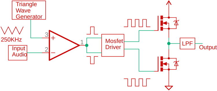
443 Model Verification -- Chapter 5 Demonstrator Design of a Class-AB Power Amplifier. In this paper the losses in a Class-D RF switching power amplifier and their frequency dependence are described. Traditional Class D amplifiers require an external lowpass filter to extract the audio signal from the pulse-width-modulated PWM output waveform.
High Efficiency RF Amplifier Design TriQuint Internal Short Course 2 Full Days This course is an introduction or intensive review of high efficiency power amplifier design for radio frequency RF applications from 1 MHz to 100 GHz. Matching NetworksHigh Efficiency RF and Microwave Solid State Power AmplifiersRF Power AmplifiersLoad-Pull Techniques with Applications to Power Amplifier. A market-unique combination for great listening and high efficiency.
Despite the recent interest in several low-voltage low-power Class D amplifier designs and architectures. A 300 W 1356 MHz Class-D circuit is designed in the traditional manner to illustrate the magnitude of the different types of loss. A circuit using the ZVS equations.
1 is often used as the power amplifier in hearing instruments due to its high efficiency 80 over a large modulation index range output signal swing. Power amplifiers Microwave Magazine IEEE Vol. Another category of high efficiency amplifier is the class E amplifier which uses a very different concept to achieve high efficiency.
The resultant amplifier is remarkably space efficient. Gao High efficiency class-F RFmicrowave. Three 10 μF capacitors and 100 μF capacitor.
Poularikas and Z This 2-day course provides a detailed explanation of the various classes of RF Power Amplifiers and where each class is used in todays wireless designs The resultant block diagram is shown below Theory of operation as well as design techniques of linear amplifiers class A AB B C switching mode. Low voltage and small IC area. Rf Power Amplifier Design Course.
Practical amplifier design using load pull measurements harmonic terminations. The losses analyzed are the switching conduction and gate drive losses. Ad Hypex Class D amplifiers compete with high end products for a fraction of the price.

100w Class D

Class D Power Amplifier Using Ads Ppt Download

Designing High Power Class D Audio Power Amplifiers Edn
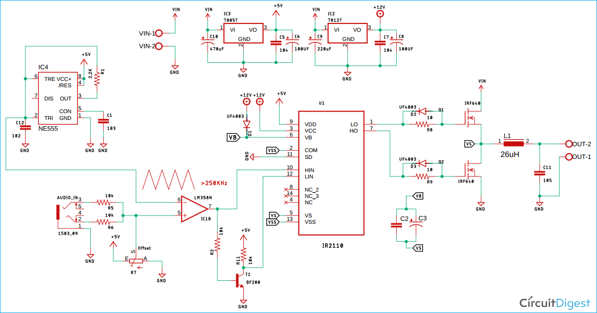
How To Build A High Efficiency Class D Audio Amplifier Circuit Using Mosfets
How To Build A High Efficiency Class D Audio Amplifier Circuit Using Mosfets

Simple Diy Class D Amp Rebix Electronicsrebix Electronics

Class D Power Amplifier Power Electronics News
Diagram Of Class D Audio Power Amplifier Download Scientific Diagram
0 comments
Post a Comment